


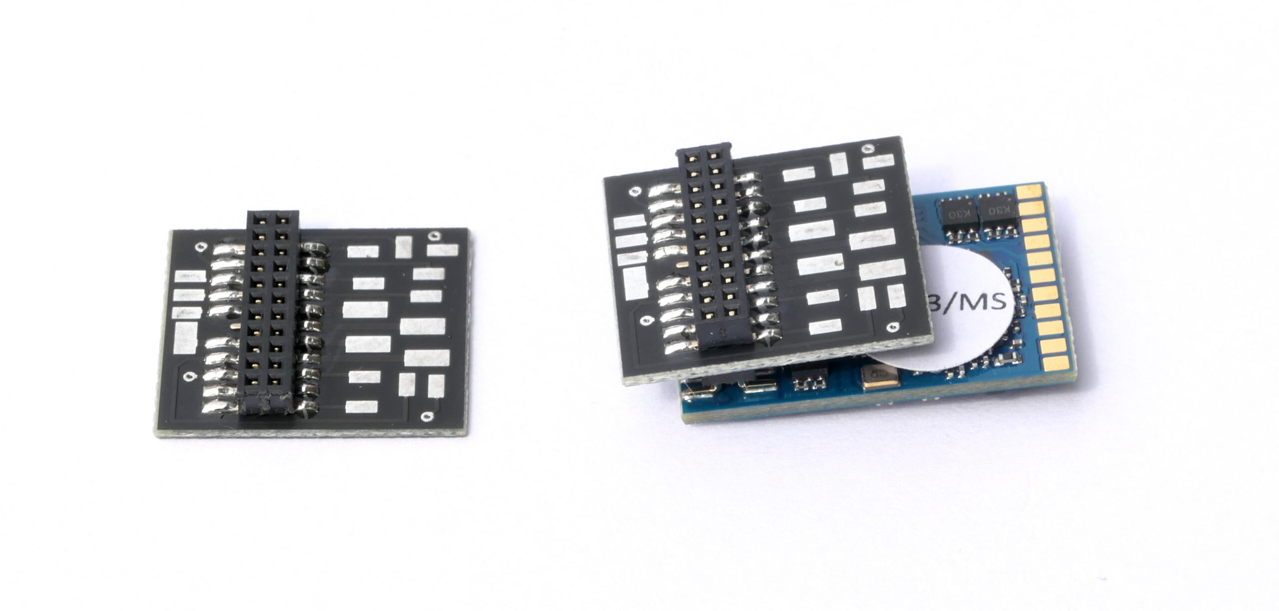
Anyone digitalising a locomotive almost always comes across two terms: PluX22 and 21MTC. Both are standardised decoder interfaces – the decoder is simply plugged in instead of soldered. Here we explain how the two differ, how the contacts are assigned and what to look out for during installation.
Key points at a glance
- Both interfaces have 22 contacts at a 1.27 mm pitch; pin 11 is missing as reverse-polarity protection.
- PluX22: all function outputs are amplified – lamps and LEDs (with a series resistor) can be connected directly.
- 21MTC: AUX3 to AUX6 supply logic level only; in return, the interface is also suitable for AC motors.
- If there is no interface in the loco, an adapter board helps – solder it in once, then just plug in the decoder.
Contents
What is a decoder interface?
A decoder interface is a standardised socket on the circuit board in the vehicle. Track, motor, lights, speaker and other functions are always on the same contacts. This means any decoder with the same interface fits – regardless of manufacturer – and can later be swapped without a soldering iron. PluX is defined in the NEM 658 and 21MTC in the NEM 660 of the European model railway association MOROP; the detailed technical specifications can be found in the RailCommunity standards RCN-122 and RCN-121.
PluX22 and 21MTC compared
PluX22 · NEM 658
- Decoder has the pins, the vehicle has the socket
- Front/rear lights and AUX1–7, all amplified
- for DC motors (including coreless motors)
- Decoder max. 30 (35) × 16 × 6 mm
21MTC · NEM 660
- Decoder has the socket, the vehicle has the pins
- AUX1–2 amplified, AUX3–6 logic level only
- for DC, coreless and AC motors
- Decoder max. 30 × 15.5 × 6.5 mm
The most important practical consequence: with PluX22 you can connect lamps or LEDs (with a series resistor) directly to all outputs. With 21MTC AUX3 to AUX6 supply only a logic signal of at most 0.5 mA; the vehicle needs an amplifier circuit on its own board for this, or you choose a decoder with amplified outputs.
Contact assignment
Select the interface to see the assignment of all contacts:
PluX22 pin assignment according to NEM 658
TrackMotorLightsOutput, amplifiedLogic level / train busSpeakerPower supplyIndex
Schematic arrangement of the 22 contacts in two rows; pin 11 is missing as reverse-polarity protection. PluX16 uses contacts 3 to 18.

| Pin | Connection | Meaning |
|---|---|---|
| 1 | GPIO_C | Input/output with logic level, e.g. wheel sensor |
| 2 | AUX3 | Output 3, amplified |
| 3 | ZBCLK / GPIO_A | Train bus clock or input/output (logic level), e.g. servo |
| 4 | ZBDATA / GPIO_B | Train bus data or input/output (logic level) |
| 5 | GND | Decoder minus |
| 6 | Cap+ | Plus for buffer capacitor |
| 7 | F0_f | Front lights (headlights, forward) |
| 8 | Motor + | Motor (amplified output on function decoders) |
| 9 | U+ | Decoder plus (common plus of the functions) |
| 10 | Motor − | Motor (amplified output on function decoders) |
| 11 | Index | not assigned – reverse-polarity protection |
| 12 | Right rail | Right-hand current pickup (3-rail: centre pickup) |
| 13 | F0_r | Rear lights (headlights, reverse) |
| 14 | Left rail | Left-hand current pickup (3-rail: wheels) |
| 15 | LS_A | Speaker A |
| 16 | AUX1 | Output 1, amplified, e.g. tail light (reverse) |
| 17 | LS_B | Speaker B |
| 18 | AUX2 | Output 2, amplified, e.g. tail light (forward) |
| 19 | AUX4 | Output 4, amplified |
| 20 | AUX5 | Output 5, amplified |
| 21 | AUX6 | Output 6, amplified |
| 22 | AUX7 | Output 7, amplified |
21MTC pin assignment according to NEM 660
TrackMotorLightsOutput, amplifiedLogic level / train busSpeakerPower supplyIndex
Schematic arrangement of the 22 contacts in two rows; pin 11 is missing as reverse-polarity protection. In the rotated mounting position the assignment is mirrored.

| Pin | Connection | Meaning |
|---|---|---|
| 1 | GPIO_A / AUX7 | Sensor input A or output 7 (logic level) |
| 2 | GPIO_B / AUX8 | Sensor input B or output 8 (logic level) |
| 3 | AUX6 | Output 6 (logic level) |
| 4 | AUX4 | Output 4 (logic level) |
| 5 | ZBCLK / GPIO_C | Train bus clock or input/output, e.g. servo |
| 6 | ZBDATA / GPIO_D | Train bus data or input/output |
| 7 | F0_r | Rear lights, amplified |
| 8 | F0_f | Front lights, amplified |
| 9 | LS_A | Speaker A |
| 10 | LS_B | Speaker B |
| 11 | Index | not assigned – reverse-polarity protection |
| 12 | Vcc | Internal decoder voltage (optional) |
| 13 | AUX3 | Output 3 (logic level) |
| 14 | AUX2 | Output 2, amplified |
| 15 | AUX1 | Output 1, amplified |
| 16 | U+ | Decoder plus, buffer capacitor connection |
| 17 | AUX5 | Output 5 (logic level) |
| 18 | Motor − | Motor (AC motor: field coil B) |
| 19 | Motor + | Motor (AC motor: field coil A) |
| 20 | GND | Decoder minus |
| 21 | Left rail | Left-hand current pickup (3-rail: wheels) |
| 22 | Right rail | Right-hand current pickup (3-rail: centre pickup) |
What to look out for during installation
Mind the index pin: The missing pin 11 must match the blocked hole. Never force the decoder on – if it is plugged in the wrong way round, it can be damaged.
- 21MTC: compact or rotated? Usually the decoder sits with the socket facing up, and the pins pass through the decoder board. Some vehicles use the rotated mounting position – the assignment is then mirrored. If in doubt, consult the vehicle’s manual.
- 3-rail vehicles: The centre pickup goes to “Rail R”, the wheels to “Rail L”.
- LEDs need series resistors. The outputs switch to ground; the voltage comes from U+. We have suitable 0603 SMD Resistors in the shop.
- Buffer capacitor connect only to Cap+ (PluX) or U+ (21MTC) and according to the decoder’s instructions.
- Without a decoder, a vehicle with an interface will only run with a bridging plug that connects track and motor.
Practical tip: After installation, cover the solder pads of an adapter board with insulating tape. This avoids short circuits with the loco body and protects the decoder.
No interface in the loco? How to retrofit
Older models often have no interface or only an old NEM 652 socket. An adapter board helps here: you solder the loco’s wires to the labelled solder pads once, then simply plug the decoder on – and can swap it at any time later. You will find the installation instructions on the page Manuals.
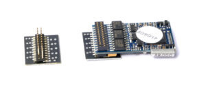
For your own circuits, the PluX22 socket and the 21MTC plug are also available individually.
Frequently asked questions
Does a PluX16 decoder fit in a PluX22 interface?
Yes, provided there is enough space. PluX16 uses the middle contacts 3 to 18; the additional outputs AUX4 to AUX7 are then not available.
Can I plug a 21MTC decoder into a PluX interface?
No. The pin assignment and connectors are different: with 21MTC the decoder has the socket, with PluX the pins. However, a suitable adapter board lets you convert the loco to the interface you want.
What do “amplified output” and “logic level” mean?
An amplified output switches lamps, LEDs or smoke generators directly. An output with logic level supplies only a control signal (max. 0.5 mA) – this needs an amplifier circuit in the vehicle.
Which interface is better?
Neither is better in principle. What matters is what is installed in the vehicle. For retrofitting where there is no existing interface, PluX22 is often more practical because all outputs are amplified; 21MTC is also suitable for AC motors.
Sources: NEM 658 (PluX) and NEM 660 (21MTC), each 2025 edition, MOROP; RCN-121 and RCN-122, RailCommunity.